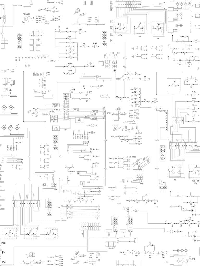
What are the P&ID Symbols Every Engineer Needs to Know?
Any industry which takes a raw material and transforms it into another finished product will face challenges specific to them and the way they streamline their operations. One such challenge is deciphering the hundreds of Piping and Industrial Diagrams (P&ID) and the symbols used as a primary means for sharing and communicating projects between people across all layers of an organization. This blog will help you identify the most important P&ID symbols used on these diagrams.
A Primer on P&ID and Its Importance
Piping and Industrial Diagrams (P&ID) are used to create important documentation for process industry facilities. These diagrams exist to allow chemical and petrochemical companies to optimize their methods as they process bulk resources into other products. To assemble these diagrams, process manufacturers use over 300 P&ID symbols as shorthand.
There are several international standards for P&ID symbols, such as the American National Standards Institute (ANSI) and the International Organization for Standardization. For the purposes of this article, we will focus on ANSI standards, although the EU, Asia, and North America have different conventions. Even with all these standards, there are exceptions to every rule, so reading and digitizing these symbols and diagrams is an exhausting endeavor.
Which P&ID Symbols are Most Important?
In order to read and understand these diagrams, users must be familiar with basic symbols. Here are some examples of instrumentation symbols and their use:
- Centrifugal pumps:
- Transport fluids to the hydrodynamic energy of the fluid flow.
- Centrifugal pumps:
- Convert the input power to kinetic energy in the liquid by accelerating the liquid with an impeller.
- Vacuum pumps:
- Remove gas molecules from a sealed volume in order to leave behind a partial vacuum.
- Gear pumps:
- Use the meshing of gears to pump fluid by displacement.
- Controllers:
- Have a variable output to regulate a controlled variable in a specific way.
- Control valves:
- Directly manipulate the flow of one or more fluid process streams.
- Pressure indicator controls:
- Regulate positive or negative vacuum pressure.
- Flow control valves:
- Regulate the speed of motors or cylinders within a system.
- Converters:
- Receive information as one form of an instrument signal and transmit an output signal as another form, such as a current-to-pneumatic signal converter.
- Condensers:
- Devices for reducing gas or vapor to liquid.
- Furnaces:
- Used for heating.
- Boilers:
- Closed vessels in which water or other fluid is heated—not necessarily boiled.
- Motors:
- Create motion. They usually refer to an engine of some kind.
- Reducers:
- Reduce the pipe size from a larger to a smaller bore (inner diameter).
- Separators:
- Mechanical devices which separate fluids and solids.

DataSeer: Where AI and Industrial Diagrams Meet
As mentioned, there are over 300 P&ID symbols, so knowing what all of them represent is very difficult. Then, once you do know them, you need to apply them to industrial diagrams. Analyzing diagrams by hand can take hours or even days.
This is where DataSeer comes in. Our artificial intelligence (AI) platform is designed to read and analyze industrial diagrams, saving you time and your organization money. With DataSeer, you can automate the process of interpreting P&ID symbols, reducing errors and increasing efficiency.
Visit DataSeer’s website and schedule a demo to see the platform in action. Discover how our cutting-edge AI technology can revolutionize the way you work with P&ID symbols and industrial diagrams.
